In motor drive applications, the position and speed feedback loops are usually required, as shown in Fig. This link plays a key role in the performance of the system. Nowadays, there are many kinds of measurement position and speed sensing technology on the market, which can meet the needs of users for different precision applications. Among them, the rotary transformer is a reliable measuring position, speed sensor, widely used in industrial drive and new energy vehicles. By reading this article, you can learn: what is the spin, how it works, the relevant applications of the spin and what programs are present on the market today.
 Figure 1 basic block diagram of the motor drive system
1. What is a rotary transformer?
Rotary transformer (Resolver), referred to as the rotation, is an electromagnetic sensor, used to measure the rotation of the angular displacement and angular velocity. As shown in Figure 2, the rotation consists of a stator and a rotor, which is usually fixed to the motor shaft and rotated synchronously.
 Figure 2 Rotary transformer physical map
2. How does the rotation work?
Analog general transformer principle, the rotary transformer stator winding as the primary side of the transformer, accept the excitation voltage. The rotor winding is used as the secondary side of the transformer and the induced voltage is obtained by electromagnetic coupling. Rotor winding output voltage amplitude and the rotor angle into a sine, cosine function, as shown in Figure 3. The analog signal is converted to the output signal, the arctangent value is calculated, the current angular displacement of the rotor can be obtained, and the differential of the angular displacement to time is the rotational speed.
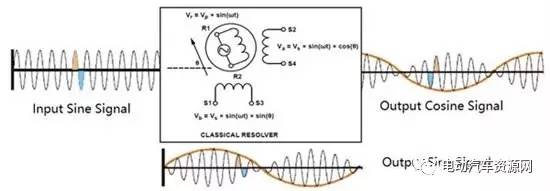
Figure 3 working principle of the rotary transformer
In addition, the rotary transformer in order to work, and ultimately, the help of the peripheral circuit in Figure 4.
In order to drive the rotation, need to boost the chip and field op amp. Boost chips are typically used to power the field op amps and rotations. The field op amp is used to generate a sine wave input signal. The rotation requires the use of this signal to produce the corresponding sine, cosine output signal.
The output of the swivel is an analog signal that requires the analog front end (AFE) to filter the signal and adjust it back to the MCU for angular calculation. The Rotary Digital Converter (RDC) is used to convert sinusoidal, cosine analog signals into digital signals. The output terminal can transmit the displacement and speed information to the MCU through various communication methods, such as SPI, parallel interface, simulation encoder interface, analog interface and so on. Finally, the system between the sensor and electronic components also need a variety of protection and fault detection functions, such as overcurrent protection, overvoltage protection, short circuit protection, overheating protection.
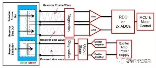 Figure 4 Rotary transformer external circuit topology
3. What are the typical applications of the spin?
Because of its internal non-electronic components, so the rotary transformer can be well adapted to high temperature, dust, high speed (8000r / m above), high vibration and other working environment. This also makes the rotation have a longer service life than other sensors.
Rotation of the above characteristics make it the industrial, automotive applications, one of the most ideal sensor, as shown in Figure 5. In industrial applications, the rotation is widely used in servo control systems (such as elevators), industrial robots, AC variable frequency drive, plastic pressure system, textile systems, metallurgical systems. In automotive applications, the cyclone is widely used in electric, hybrid car traction inverter, HVAC systems, starting and stopping generators and power steering systems.
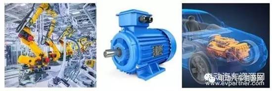 Figure 5 Typical applications of rotary transformers
4. Existing spin solutions
At present, the market's existing spin solutions are mostly discrete, the topology shown in Figure 6. The program BOM cost is high, accounting for a large area. At the same time, the discrete design requires longer development time. Especially the development of new platforms, developers need to debug the design to adapt to different models of the rotary sensor.
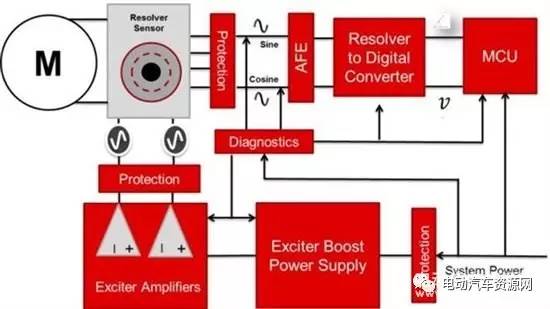
Figure 6 Alternative scheme of the existing spin interface
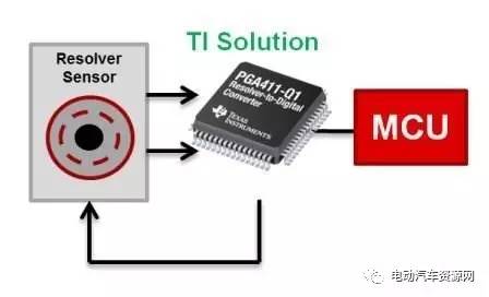 Figure 7 TI spin interface integration scheme topology
In order to simplify the design, Texas Instruments (Texas Instruments) provides PGA411-Q1 spin interface chip, as shown in Figure 7. PGA411-Q1 integrated excitation op amp, boost DC-DC chip, analog front end (AFE), rotary digital converter (RDC) and a variety of protection, fault diagnosis function in one. Using the chip, the system can be simplified into three parts: the rotary sensor, the PGA411-Q1 and the MCU. In addition, the chip provides the following advantages for applications:
Simplify the system: Highly integrated reduces the BOM cost and PCB cost of the entire system.
Save development time: shorten the development cycle. Engineers do not need to change the external circuit, only by modifying the register to adjust the external output signal. It is compatible with different platforms and different models.
Conforms to the SafeTI ™ standard to ensure functional safety: Assist the system through functional safety standards up to ASIL D (ISO26262).
5.PGA411 + C2000 complete solution
The PGA411-Q1 can also be used with the C2000 platform to provide a complete TI solution. In addition to the functional safety standards of the PGA411-Q1, the C2000 Delphino series meets ASIL-B safety standards. PGA411-Q1 has a wealth of development tools and reference materials. The PGA411-Q1 evaluation board helps you quickly develop and use the PGA411-Q1. The other two reference designs: TIDA-00363 for industrial applications, TIDA-00796 for automotive applications. Both for the C2000 evaluation board LAUNCHXL-F28069M, are plug and play compatibility, the above tools, data can make development more simple and convenient.


 RCCN WeChat QrCode
 Mobile WebSite