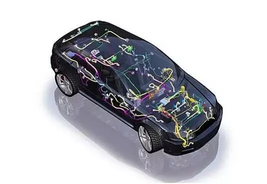
Abstract: The wire harness design includes the electrical functions and electrical requirements to be achieved by the wire harness, the size of the wire harness, the protection and fixing methods, and the connection between the wire harness and between the wire harness and the vehicle electronics.
As people's requirements for the safety, comfort, and economy of automobiles have become higher and higher, the electrical configuration and functions of automobiles have become more and more, so the wiring harness connecting various electrical devices has become more and more complicated, becoming a contemporary automobile. The frequent occurrence of failures has also received increasing attention in automotive design and manufacturing. The following briefly describes the design of automotive wiring harness work.
First, schematic design and calculation
1.1 According to the "Electrical Design Mission" requirements of the electrical configuration and technical requirements to draw electrical schematics.
1.2 Determine the insurance capacity and wire size according to the power of each appliance. At the same time, perform load distribution for each electrical subsystem to determine the total insurance capacity.
1.3 Calculate the wire diameter:
According to the formula
Medium: I - current, A; P - electrical device power, W; U - voltage, V; A - wire diameter, mm2; ρ - copper resistivity (about 0.0185 Ωmm2/m); L = Lead length, m; U - allows maximum voltage drop loss.
At the same time, consider the following situations:
a. If the wire is too long, the diameter of the wire can be enlarged;
b. When the conductors are connected to the electrical appliance after being connected by multiple connectors, consider that the voltage drop of the terminal is large, and the diameter of the cable can be appropriately enlarged.
1.4 Different types of wires have different line voltage drops allowing current.
Second, draw three-dimensional wiring diagram
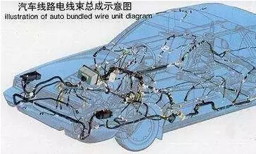
2.1 According to the location of each electrical device, determine the form of three-dimensional wiring, the current general international wiring is generally E-type and H-type;
2.2 simulation simulation of different areas of the beam diameter;
2.3 Consider harness sealing and protection.
2.4 The fixing hole position and the fixed form of the harness are determined.
2.5 Theoretically speaking, it is most reasonable to connect all the electrical components of a wire harness, but it is impossible to do the actual loading. Therefore, the wiring harness should be divided into reasonable blocks. In the case of
convenient assembly, systematic design should be adopted as much as possible.
2.6 The design of the ground connection point is very important in online beam design, otherwise it will cause signal interference and affect the function realization of certain electrical appliances. According to different models, it is designed into multiple grounding points. The design of the grounding iron should meet the following requirements:
a. The weak signal sensor should be grounded separately and nearby to ensure normal signal transmission;
b. Each ECU should be grounded separately to prevent interference;
c. Think negatively about the battery cathode and the engine and gearbox ground.

Third, design two-dimensional harness diagram
3.1 Distribution box
The power distribution box (insurance and relay) is the core of the vehicle's electrical system and plays a role in distributing the load, centralizing the power supply, saving space, simplifying the wiring harness, reducing the cost, and facilitating maintenance. Generally, it can be designed into 1 to 2 as needed.
Some of the newly developed models of the power distribution box have been combined with electronic control functions; and there is an increasing market for non-contact, non-fuse central control boxes
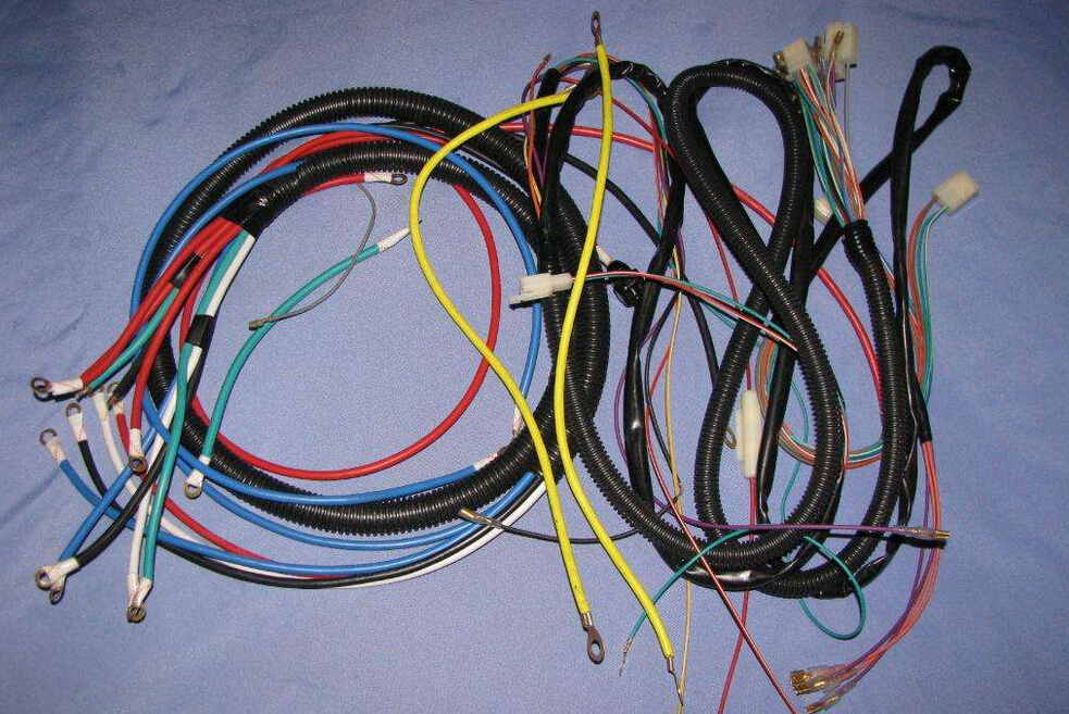
3.2 Selection of wire color
The selection of wire colors is based on ZB T 35002 "Colors of Low Voltage Wires for Automotive".
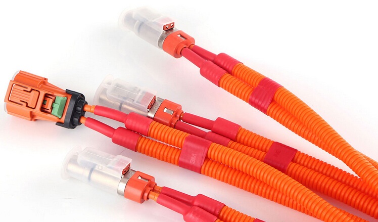
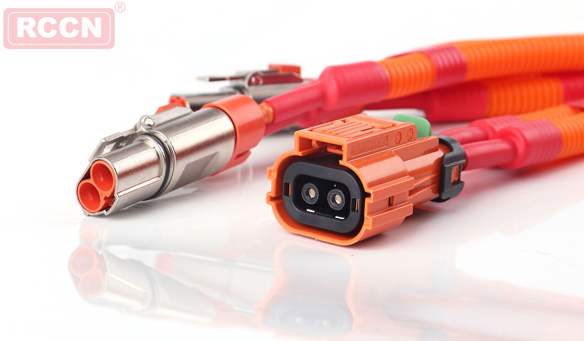
3 Selection of connectors
a. According to the wire diameter and the size of the current through the use of connectors;
b. The engine compartment selects sealed connectors;
c. Preferentially, double spring type press-fit structure connectors are used to reduce the contact resistance.
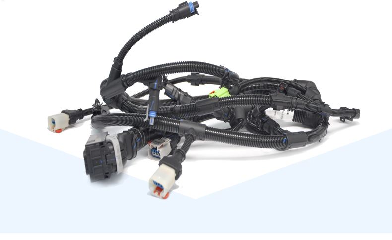
3.4 Harness Dressinga. In the cab, it is generally wound with tape;
b. The tape is generally tightly wound inside the instrument panel;
c. On the floor or away from the engine, generally use fire-retardant bellows;
e. The inside of the door and the inside of the trunk door are generally packed with adhesive tape or industrial plastic cloth;
f. Some areas close to the engine use a heat-insulating glass tube or wire wrapped glass ribbon.
In addition to the above, it should also pay attention to: the distance between the reading and writing coils and the anti-theft ECU to prevent signal transmission attenuation; each of the electrical components of the transmission signal such as "oxygen sensor", "knock sensor", "read and write coil" should be Select LE-SE signal lines or AVSS shielded lines.


 RCCN WeChat QrCode
 Mobile WebSite
