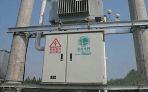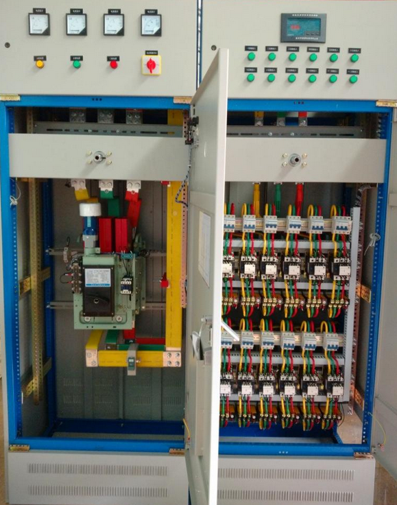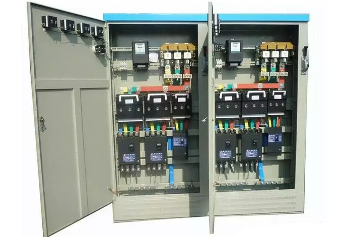
First, construction preparation
(1) Working conditions
1. The horizontal structure of the wall has been popped up.
2. The wooden bricks and iron pieces required for installing the distribution box are pre-buried.
3. The installation position of the dark assembled electrical box reserved with the civil structure is correct and the size is appropriate.
4. When the electric box body is darkly assembled, the plaster on the wall surface of the installation box should be completed. When darkly assembling the electric box core and the face, the plaster, spray and paint of the civil construction should be completed.
5. When assembling the electric box, the plastering, spraying and painting of the civil construction should be completed.
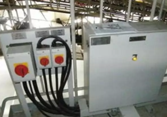
(2) Material requirements
1. The high-voltage complete power distribution cabinets and control cabinets (screens and platforms) installed in the building electrical engineering shall have the factory certificate, production license and test records. In addition to the above-mentioned quality certification documents, the low-voltage complete power distribution cabinet, power and lighting distribution box (disk, cabinet) should also have a copy of the “CCC” certification mark and certification certificate.
2, power, lighting distribution box, low-voltage cabinet, different manufacturers, different specifications of the factory certificate should be prepared separately. Low-voltage incoming redundant box or branch cabinet, multi-level entry demarcation switch cabinet, different manufacturers, different specifications of the certificate should be prepared separately.
3. After the product enters the scene, the appearance inspection is first carried out: the box body should have a certain mechanical strength, the surrounding area is smooth and no damage, and the paint does not fall off. Then carry out the simple test: all kinds of appliances in the box should be installed firmly, the wires are arranged neatly, the crimping is firm, the thickness of the second floor is not less than 1.5mm, and the flame retardant plastic plate should not be used as the second floor. Various circuit breakers are subjected to visual inspection, adjustment and operation tests.
4. The distribution box should not be made of combustible materials; in dry and dust-free places, the wooden distribution box used should be flame retardant.
5, galvanized products (bracket, cross arm, grounding pole, lightning protection steel, etc.) and external fittings should have a certificate of factory and galvanized quality certificate.
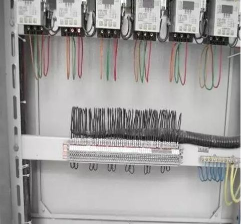
Distribution box installation requirements
1. The distribution box should be installed in a safe, dry and easy-to-operate place. If there is no special requirement for the design, the height of the bottom margin of the distribution box should be 1.5m. The height of the bottom margin of the lighting distribution board should not be less than 1.8m.
2. The wire stripping section should not damage the core or the wire core is too long. The wire head should be firm and reliable. If the multi-strand wire is connected with the terminal block, the crimping terminal (nose) should be installed, and then tinned together, then pressed. Press on the terminal block. If it is connected with the crimping hole, the multi-strand wire should be twisted with tin and the perforation should be crimped with the top wire. Be careful not to reduce the number of wire strands.
3. When the wire is led out of the panel, the panel hole should be smooth and burr-free, and the metal panel should be provided with an insulating protective cover. In general, only one thread is worn in one hole, except for the following:
(1) Indicator wiring;
(2) The total gate wiring number for controlling the two trips is the same;
(3) One hole into the multi-wire wiring.
4. The screw fuse installed in the distribution box should be connected to the terminal of the intermediate contact, and the load line should be connected to the terminal of the screw.
5. The position of the disc brakes in the distribution box should correspond to the branch road. A card frame should be installed under the switch box to indicate the name of the circuit.
6. AC, DC or different voltage level power supplies in the distribution box should have obvious signs.

7. All kinds of knife gates and automatic switches installed on the panel of the distribution box. When the circuit is in the open state, the movable part of the blade should not be charged (except in special cases).
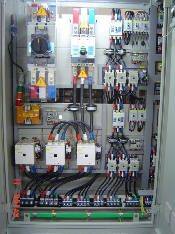
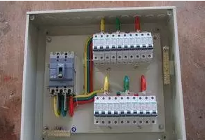
8, the small busbar on the distribution box should have yellow (Ll phase), green (.L2 phase), red (L3 phase), light blue (N zero line) and other colors, yellow and green two-color line for the protection ground .
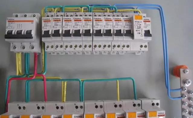
9. The electrical tools and instruments on the distribution box should be firm and tidy, evenly spaced, the copper terminals are not loose, the opening and closing is flexible, the parts are complete, and the arrangement spacing should meet the requirements of the following table.
First notice that the bridge inside is installed horizontally and vertically, and the accessories are set according to the standard.
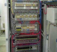
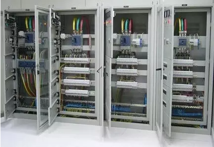
1. The power distribution cabinets are arranged in rows, and the power distribution cabinets are connected with each other or with the basic steel bars by galvanized bolts, and the anti-loose parts are complete. The facade of the high and low voltage cabinet is flat and the back is flat. The level and verticality are good and the operation channel is spacious. The front side should have a face number, and the back should also be numbered. The internal wiring is neat and the reading is correct. Terminals must be numbered;
2. Never allow any water supply and drainage pipes to pass;
3. The neutral point on the low voltage side of the transformer is directly connected to the grounding trunk, and the basic steel is grounded;
4. There should be signs on the ends of the cable terminals, joints, bends and shafts;
5. The power distribution cabinet should have a common steel base, the overall layout is neat, and the wiring inside the cabinet is correct and reliable. The trench cable is arranged neatly on the bracket, bundled in sections, and has a listing. The grounding strip layout specification is clear and the insulation board is properly set.
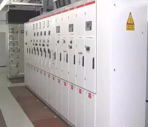 The bridge frame is set up with specifications, the grounding protection is reliable, the cable enters the cabinet with reasonable force and the outer protection is good. In the substation, high and low voltage power distribution equipment and bare busbars should be installed directly above the luminaire.
1. All voids in the power distribution room and the partition wall or floor should be sealed and sealed.
2. The length of the power distribution cabinet is more than 6 meters, there must be two exits on the back, and the minimum width is 1 meter.
3. The mouse board must be installed at the door.
4. The rubber plate should be laid in the front working area of the power distribution cabinet.
5. The insulation resistance feeding line between the cabinet and the wire and the ground to the ground is greater than 0.5 megohms, and the secondary circuit is greater than 1 megohm. The cables are neat.
The practice of blocking the mouse board: generally 30cm piece, a total of two pieces, using insulated bakelite or plastic hard rubber board.
The power distribution room should be suspended once.
1. The iron fire door and frame of the power distribution room shall be connected with the grounding trunk wire by copper braided wire;
2. Reserve no less than two grounding spare points in the power distribution room, and place bolts, flat washers and spring washers.
The grounding trunk line is generally laid out.
1. The height from the ground is 250-300mm, and the gap between the walls is 10-15mm.
2, each section 15-100mm, yellow and green.
3. The horizontal bracket is 0.5-1.5 meters, the vertical support is 1.5-3 meters, and the curved part is 0.3-0.5 meters.
4, elbow special processing.
Main grounding practice →
Emphasize:
1. When the cable passes through the zero-sequence current transformer, the grounding wire of the cable head should be grounded through the zero-sequence current transformer; the cable sheath to the cable metal sheath and grounding wire passing through the zero-sequence current transformer should be insulated. . (This clause is for the zero-sequence current transformer to correctly reflect the operation of the cable and to prevent the influence of discrete currents, so that the zero-sequence protection error signals or actions.)
2. When connecting the cable to the air switch and other equipment, the core and the tightening bolt should be sheathed to ensure safe operation. Front panel of the control cabinet →
About cable trenches:
1. The lowermost bracket is not less than 5-10cm; the uppermost end is not less than 15-20cm.
2, the cable is placed on the shelf, the inside is dry, tidy, orderly, and the bracket is well grounded. Brackets are generally hot dip galvanized. Cable trenches should be waterproof and drained.
3. Cable access should be closed.


 RCCN WeChat QrCode
 Mobile WebSite