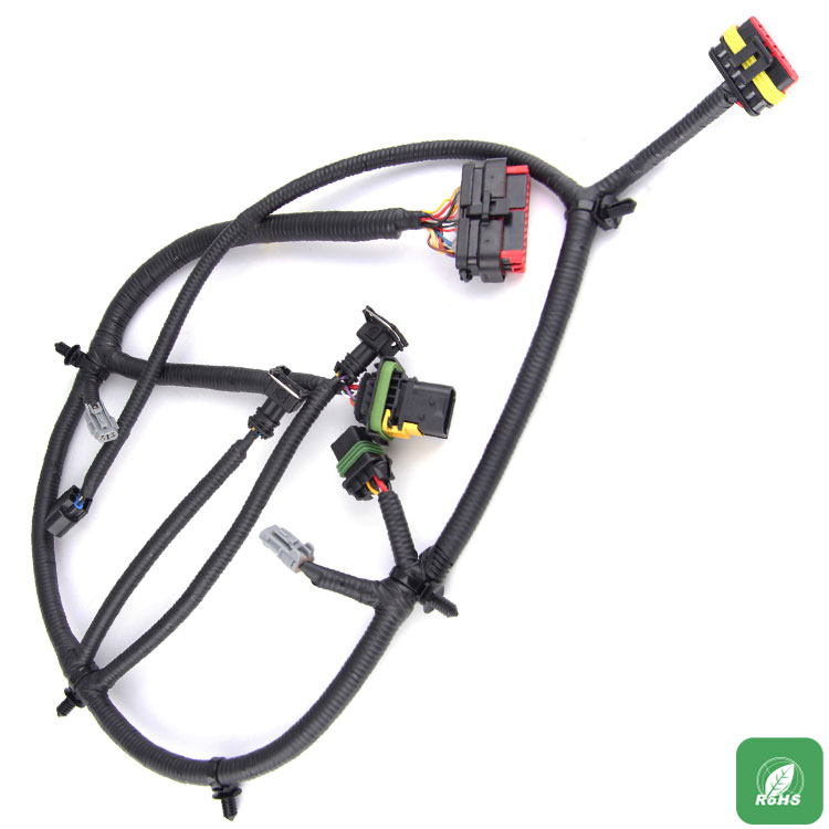
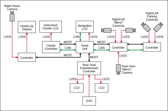
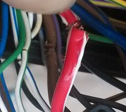
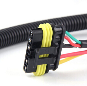
With the increase of automobile electrical equipment, the electrical functions and functional configuration of the vehicle are becoming more and more complicated, and the requirements for the design of the wiring harness are reasonable and gradually increased. At the same time, with the gradual decline in vehicle costs, the cost pressure on wire harnesses has also gradually increased. In view of the above reasons, to verify whether the design of the wiring harness is reasonable and how to optimize the wiring harness system to achieve the optimal design, the attention of these two tasks has gradually increased.
This article focuses on the necessity of wire harness design verification, several methods of design verification, and the main methods of wire harness system design verification. At the same time, combined with examples, the in-depth explanation of the wiring harness design verification part. Because the specific verification methods and evaluation standards have many details, due to space limitations, some aspects can only be briefly explained. I. Necessity of designing and verifying the wiring harness system The wiring harness connects all controllers, actuators, and sensors on the vehicle, and plays the role of power distribution and signal transmission in the vehicle. Taking the human body as an analogy, the wiring harness is equivalent to the blood vessels and nervous system in the vehicle. Therefore, whether the wiring harness design is reasonable or not directly affects the electrical safety of the vehicle and the reliability of the vehicle.
If the wiring harness design is unreasonable and cannot meet the requirements of the actual vehicle load, then there will be accidents such as short fuse life, abnormal melting of fuses, overloading of smoke and even fire. If the amount of redundant wiring harness design is too large, it is not conducive to vehicle cost control, and it is not conducive to vehicle quality and fuel economy.
In summary, the reasonable and appropriate design of the wire harness and the optimization of the wire harness design have become the focus of more and more OEMs and wire harness manufacturers. Combined with the product's forward development model, the entire design process is complete, controllable and optimal through the closed-loop approach of design-verification-optimization (Figure 1).
1) Software simulation
The advantage is that it can be implemented during the forward design phase. Through software simulation, it is verified whether the assembly of the wiring harness is reasonable, the topology of the entire vehicle wiring harness is appropriate, the design of the power distribution principle and the arrangement of electrical components are reasonable. However, the software simulation is based on the calculated parameters to simulate the simulation, which cannot realize the test and verification of the actual vehicle conditions and the various operating conditions of the actual vehicle.
The wire short test mainly verifies whether the matching relationship between the wire and the fuse is appropriate. It is usually tested on a bench or a real car. Under normal load conditions, the power supply circuit is directly shorted or overloaded. Check whether the fuse is blown in time during the test to protect the wires.
During the overload test, 135% and 20% of the normal working current value of the electrical load is used as the overload current test. It is also necessary to ensure that the fuse is blown in time during the period when the temperature rise of the conductor is within a reasonable range; or during the overload process, the controller / The actuator starts overload protection in time to avoid the continuous occurrence of overload current. Example: In a certain model project, when the blower circuit was overloaded by 135%, it was found that the blower speed regulation module was burned out before the fuse was blown.
The grounding system test mainly verifies the current distribution of the grounding points of the wire harness. The grounding point has a fault phenomenon when it is loose, whether there is a reverse current or a latent path, and whether there is a serious electrical malfunction. Avoid butterfly effects or seriously endanger driving Safe failure phenomenon.
It is usually tested on a real car. Under the condition that the load is working normally, the current distribution of each ground point is tested, the current distribution is recorded, the matching relationship between the current and the conductor is analyzed, and the potential of each ground point is equal.


 RCCN WeChat QrCode
 Mobile WebSite